Arb Cksa12 Compressor Wiring Diagram

The arb air locker is a unique air operated unit for which the locking action is controlled by the driver with a push of a button inside the cab.
Arb cksa12 compressor wiring diagram. For the wiring loom to follow. Many arb distributors around the world. 1 switch cover compressor 180212 4 included x2 in head assembly 310102. How to wire an arb dual compressor ckmta12 and air locker solenoids to an spod.
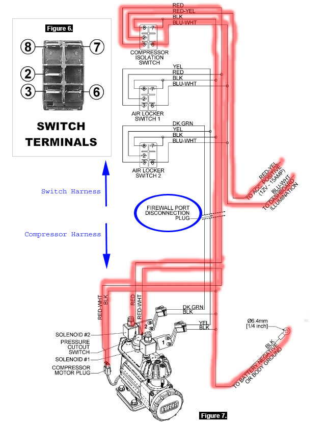
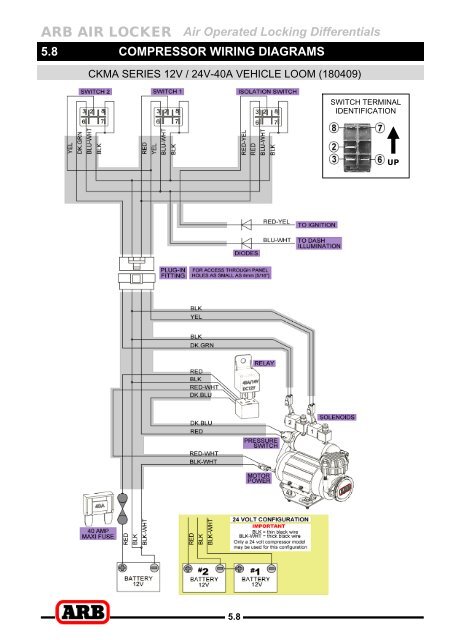
Page 15 air locker solenoid s to an arb air compressor all connections can easily be set up using only the supplied wiring loom arb 180409 shown in figure 7 consulting the wiring diagram fig 7 for wire colors and the switch terminal illustration fig 8 plug each of the female spade terminals onto their appropriate switch terminal. How to wire an arb dual compressor ckmta12 and air locker solenoids to an spod. Arb air locker air operated locking differentials 5 8 5 8 compressor wiring diagrams cksa12 12v 15a vehicle loom 180408 switch terminal identification up. 1 installation guide 2102sa12 6 for wiring diagram refer to section 5 8.
Arb part 180409 air compressor loom wiring diagram. 100 drive to each wheel when the unit is locked up. 1 switch 180209 1 wiring loom cksa12 180408 6 5 available only in packs of 3. The arb ckma12 and ckma24 compressor kits were designed specifically as a versatile quick installing compact yet high flow air source to suit the arb air locker which also suits the harsh and.
Arb recommends that you have your arb air compressor installed by a trained professional. A 12 volt air compressor 24 volt also available engages the unit in approximately 1 second and can be engaged at any vehicle speed. Join the crew http. 7 air filter assembly comes complete with.
12v model ckmta12 and 24v model ckmta24 is certified compliant to en 55014 1 as nzs cispr 14 1 and meets or.


